
Residential Irradiance Sensor
Overview
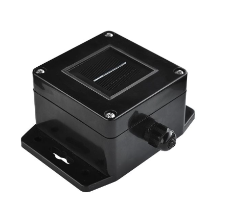
The Residential Irradiance Sensor is designed to measure irradiance for residential, rooftop, or small-scale PV projects. While industrial, commercial, and utility-scale PV systems require advanced features and high-accuracy meteorological sensors, these demands are less critical for residential and small-scale applications. The 3S-IS-LR Irradiance Sensor is a cost-effective option for measuring irradiance data for residential PV installations. As a supported Modbus output device, the Residential Irradiance sensor communicates to the eGauge using the RS-485/USB converter.
OEM Data Sheets
Configuration Tool & Modbus Map
Included Hardware
- 3S-IS-LR Sensors Irradiance Sensor
Additional needed Hardware
- RS-485/USB converter (not included)
- 12 VDC - 30 VDC power supply (not included)
Installation and Wiring
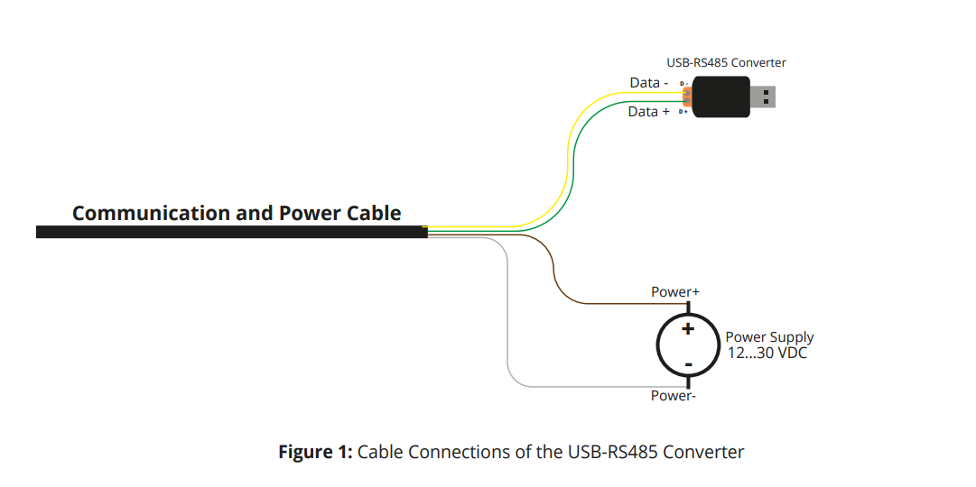
Wire the Irradiance Sensor to the eGauge RS-485/USB converter and power supply using the chart and example diagram below for guidance:
| Irradiance sensor wire | Connect to |
| Yellow | D - on RS-485/USB converter |
| Green | D + on RS-485/USB converter |
| Brown | + power supply, 12 Vdc - 30 Vdc (not included) |
| White | - power supply, 12 Vdc - 30 Vdc (not included) |
Configuration
Configuration for EG4xxx using RS485-USB adapter
The RS485-USB adapter does not require any configuration on the adapter side. However, it's important to note which USB port is in use by the adapter. It's also necessary to ensure the termination switch is set to "on" when used with the 3S-IS-LR Sensor.
Add to 'Remote Devices'
- Under the "Remote Devices" section, click "Add Device" to add a new remote device.
- Enter a suitable device name. This field is arbitrary but should make sense to the end user.
- Click the "Edit" button, and set the protocol to "Serial"
- Enter the device address. This will be
modbus://3S-IS.1@USBXwhere X is the USB port (1 or 2). The value after the dot is the sensor Modbus ID which defaults to 1 but may have a different value if it was changed using the manufacturer's software utility.
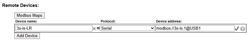
- Click the gray "?" next to the device address field. After a few seconds, this should turn into a green check mark as shown in the image above.
- To save these settings, click the "Save" button at the bottom of the page.

Add to 'Registers'
- Ensure a green check mark is shown next to the remote device address. If a gray "?" is shown, click it and wait for it to turn into a green check mark.
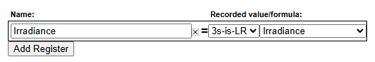
- On the Installation page, navigate to the "Registers" section and click "Add Register".
- Enter a suitable register name. This field is arbitrary but should make sense to the end user.
- The default register type will be set to "P". Click the dropdown menu and select the remote device name for the 3S-IS-LR sensor that you added in the previous steps.
- A second dropdown menu will appear. Select the remote register to record. Irradiance is the only detected value that will yield a value from the 3S-IS-LR model sensor.
- To save these settings, click the "Save" button at the bottom of the page. The meter will reboot.
- Once the meter reboots, the RX and TX LEDs on the RS-485/USB adapter should be blinking.

Viewing Data
The data recorded from the 3S-IS-LR sensor can be viewed like any other data point recorded by the meter. To see this data, navigate to the main graph page and select the appropriate register(s) from the list under the main graph.